Designing a gear reducer, also known as a gearbox, is a complex engineering challenge that requires a deep understanding of mechanical principles, material science, and application-specific requirements. This comprehensive guide aims to break down the process into manageable steps, ensuring that even those with a limited technical background can grasp the basics of gear reducer design. The goal is to provide a foundation that will enable you to design a gear reducer that meets your specific needs in terms of efficiency, durability, and performance.
Introduction to Gear Reducers
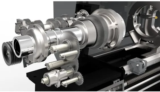
A gear reducer is a mechanical device used to reduce the speed of an input shaft (from a motor, for example) while simultaneously increasing the torque. This process is fundamental in machinery and applications where the direct output of an engine or motor is not suitable for the task at hand. Gear reducers are critical components in a wide range of industries, including automotive, aerospace, manufacturing, and robotics.
Understanding the Basics
Before diving into the design process, it's crucial to understand the key components of a gear reducer:
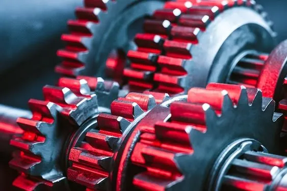
- Gears: The heart of the reducer, gears come in various types (spur, helical, bevel, and worm) and sizes, influencing the reduction ratio and efficiency of the gearbox.
- Shafts: These are the input and output axes of the gearbox. Their alignment and size are critical for transferring power efficiently.
- Bearings: Bearings support the shafts, allowing them to rotate smoothly and with minimal friction.
- Housing: The housing contains all the internal components, providing protection and structural support.
Step-by-Step Design Process
1. Define Application Requirements
The first step in designing a gear reducer is to clearly define the application requirements. This includes the desired input and output speeds, torque requirements, the direction of rotation, and any space or weight constraints. Understanding the environment in which the gear reducer will operate is also crucial, as this can affect material selection and the need for additional features like sealing or cooling.
2. Select the Type of Gear
Based on the application requirements, choose the type of gear that best fits the needs. Each gear type offers different characteristics:
- Spur gears are efficient and suitable for high-speed applications but can be noisy.
- Helical gears offer smoother operation and higher load capacity than spur gears.
- Bevel gears are used for changing the axis of rotation, ideal for right-angle configurations.
- Worm gears provide high reduction ratios in a compact size but with lower efficiency.
3. Determine Gear Ratio
The gear ratio is the ratio of the number of teeth on the output gear to the number of teeth on the input gear. This ratio determines the speed reduction and torque increase provided by the gearbox. Calculate the gear ratio based on the required input and output speeds.
4. Design Gears and Shafts
Once the gear type and ratio are determined, design the gears and shafts. This involves calculating the dimensions, materials, and heat treatments needed to withstand the operational loads. Factors such as bending stress, surface durability, and gear tooth profile must be considered.
5. Select Bearings and Housing Material
Choose bearings that can support the calculated loads and speeds. The housing material should provide adequate strength and stiffness, as well as resistance to environmental conditions. Common materials include cast iron, steel, and aluminum.
6. Incorporate Safety Factors
Include safety factors in your design to account for unexpected loads or conditions. This ensures that the gear reducer can operate reliably under peak loads and extends its service life.
7. Create Detailed Drawings
With all calculations and selections made, create detailed engineering drawings. These should include all critical dimensions, tolerances, materials, and any special manufacturing instructions.
8. Prototype and Test
Before moving to production, build a prototype of the gear reducer. Testing the prototype under real or simulated operating conditions is essential to validate the design and make any necessary adjustments.
Designing a gear reducer requires careful consideration of mechanical principles, material properties, and application-specific requirements. By following the steps outlined in this guide, you can create a gear reducer that meets your needs in terms of performance, efficiency, and reliability. Remember, the key to successful gear reducer design is in the details—thorough planning, precise calculations, and rigorous testing will lead to the best results.